Информационные технологии
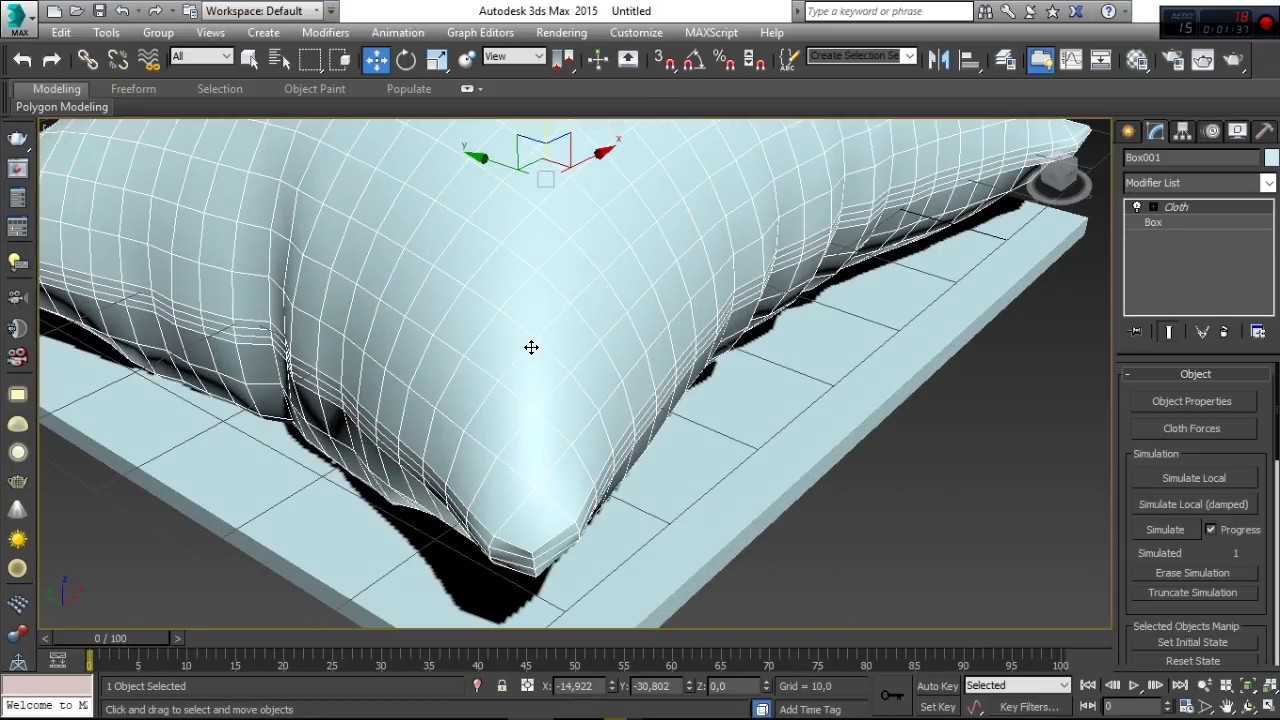
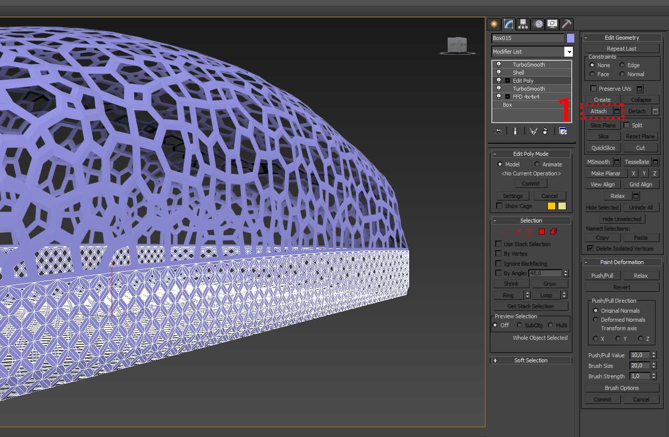
Модификатор «Cross Section»
|
Pdf ko’rish
|
… 9 …
3D-MAX-CHast-II-Uchebno metodicheskoe-posobie-Egorov-D.A.- -Kazan-KGASU-2020g.- -44-s.Language and culture~$http1-топшириқ TAQDIMNOMA HOLATI 1-TOPSHIRIQ QA JAVOBYarimo‘tkazgich asboblar yarimo‘tkazgichlar va ularning xossalar3D-MAX-CHast-II-Uchebno metodicheskoe-posobie-Egorov-D.A.- -Kazan-KGASU-2020g.- -44-s.Infarmatika va AT 44,45,46 mavzu9-sinf-informatika-va-at1.Masalalarni-kompyuterda-yechish-bosqichlariКРИТЕРИЙ 2020Ravish so’z turkumiRavish so’z turkumi8 Zardushtiylik
- Bu sahifa navigatsiya:
|
Модификатор «Cross Section» 15 16 Do’stlaringiz bilan baham: |
… 9 …
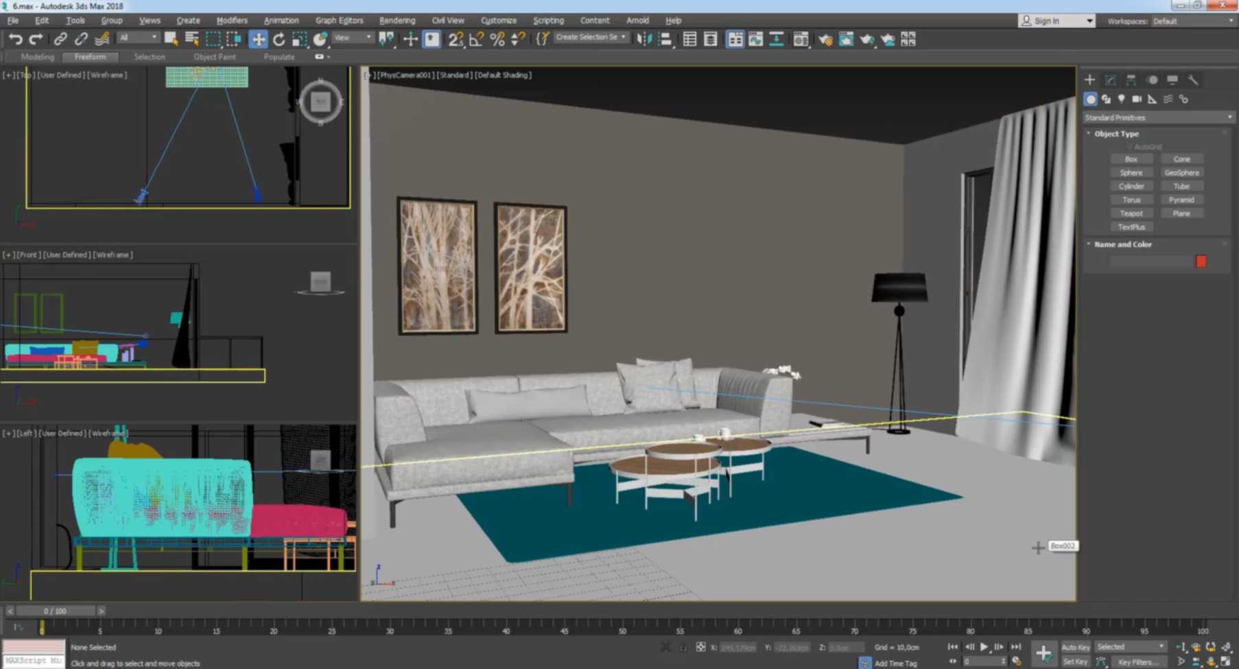
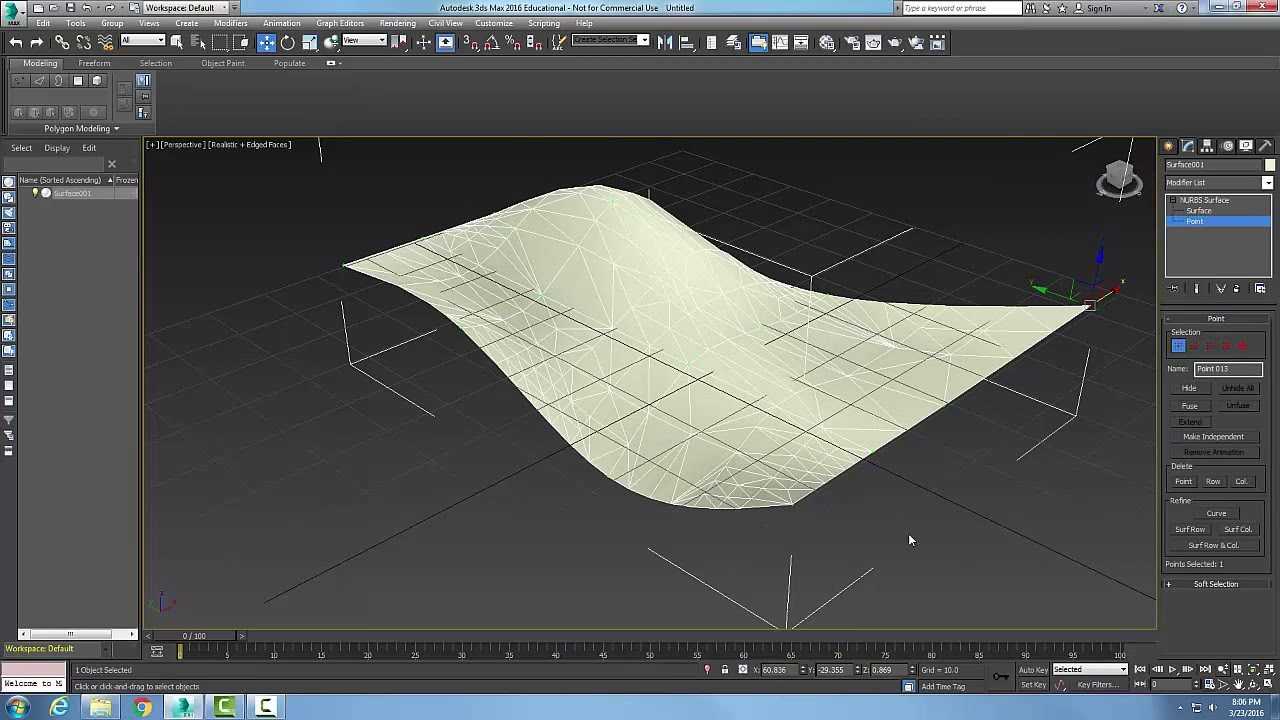
ProOptimizer
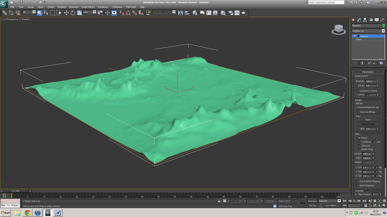
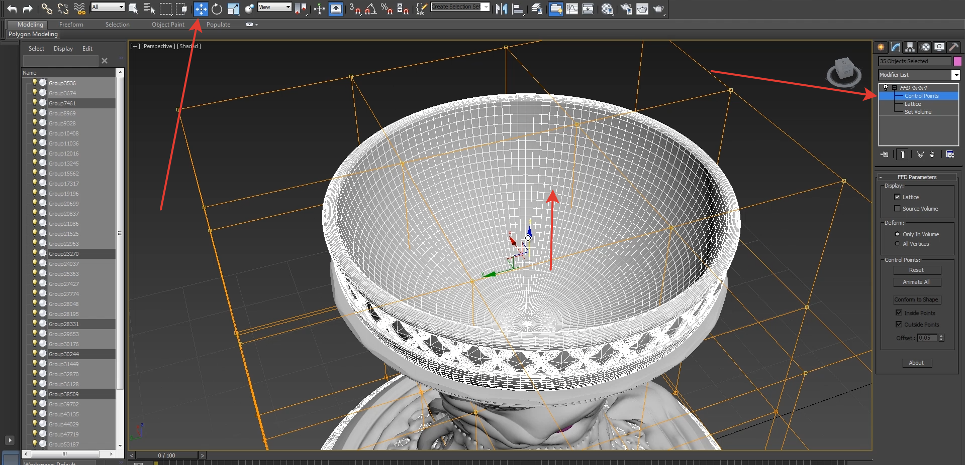
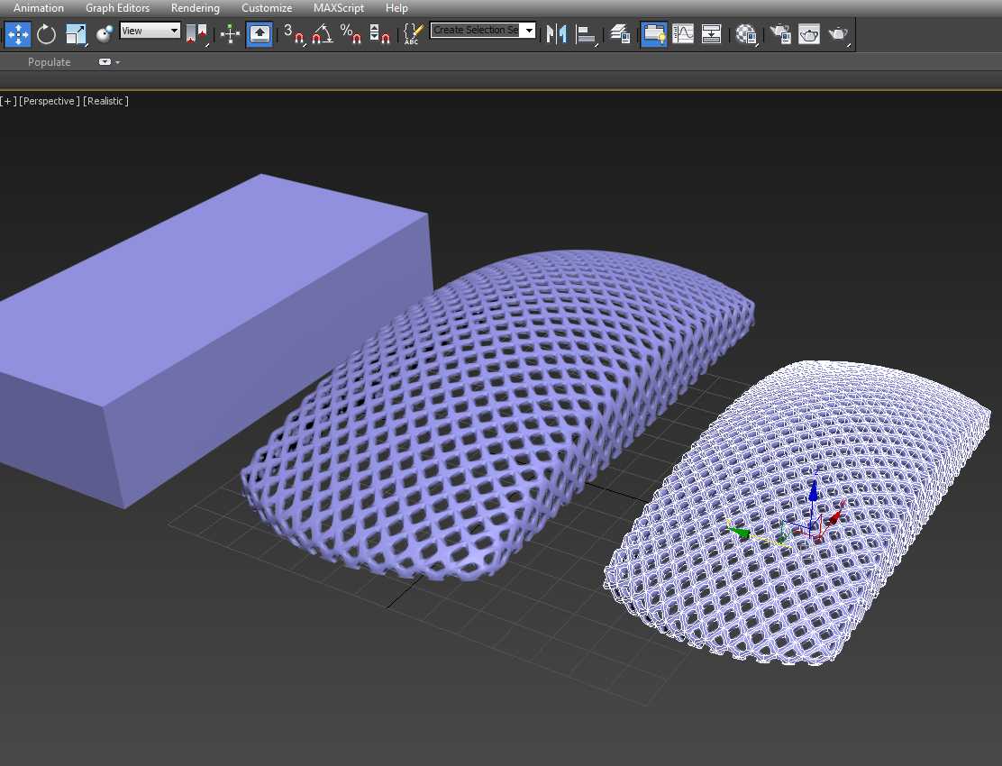
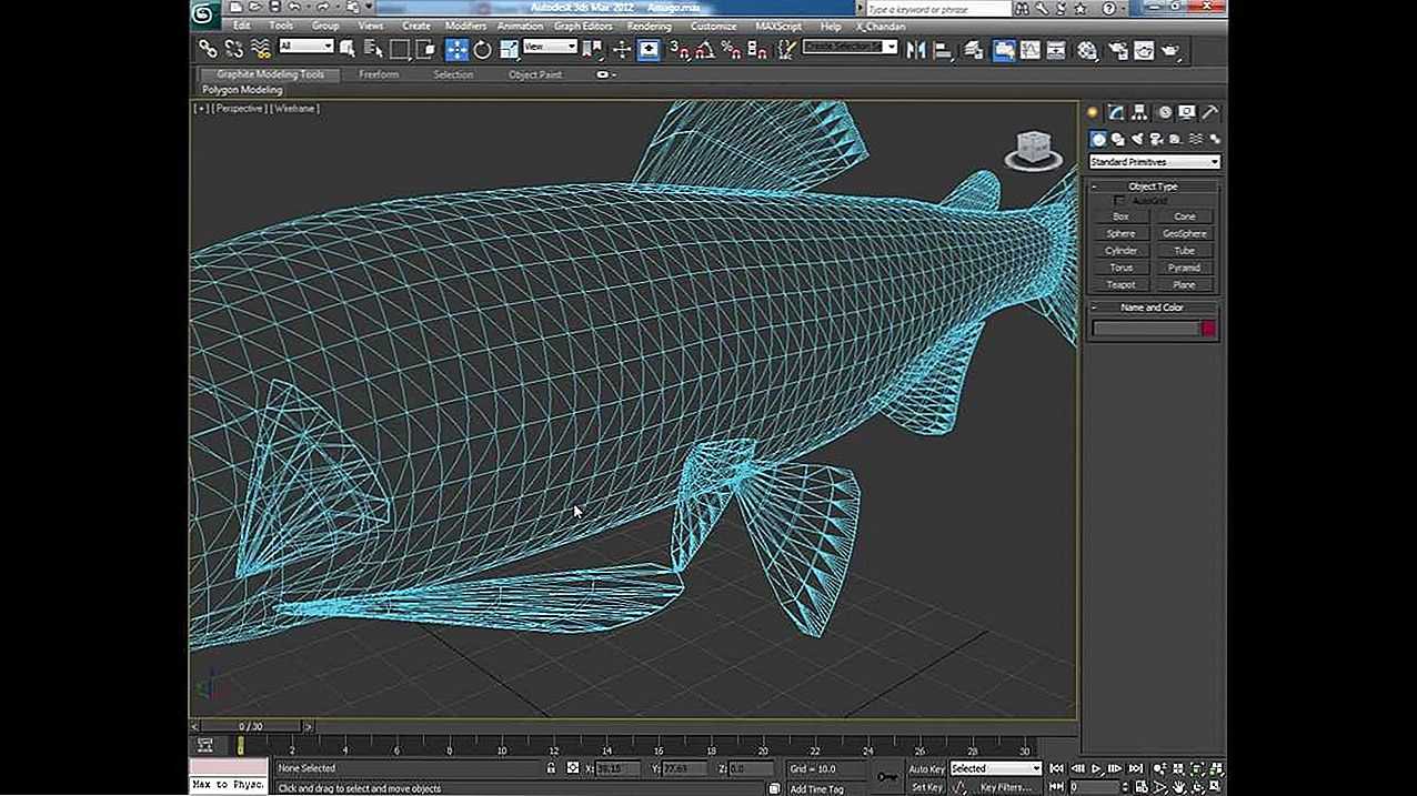
Принцип работы ProOptimizer очень схож с Optimize, но более автоматизирован. Он не имеет различных параметров настройки новых граней, из-за чего оптимизация менее гибкая. Но сам объект после оптимизации лучше сохраняет форму при меньшей трате времени на настройку. Лучше всего это будет видно на сложных объектах.
В разделе Optimization Level находятся все главные параметры и информация. Сначала вы должны рассчитать оптимизацию кнопкой Calculate, а затем поменять количество точек до результата, который вас устроит. Statistic (Before / After) показывает, на сколько было уменьшено число точек и «фейсов».
![]()
Structural cross section
A structural cross section is made to show the shape of a geological structure so as to evaluate the relationship of fluid contacts and compartments to that structure. Such features as spill points, rollover on faults, and fault geometry give an indication of the likely limits of field production. The form of a structure also provides information about its history and thus possibly the history of reservoir formation and oil migration.
Choice of datum
For a structure cross section, the datum is sea level, with data plotted above or below that point according to its present position (see Figure 1b).
Orientation and layout of a cross section
Linear cross sections are preferably oriented perpendicular to the major structural trends (dip or transverse sections). Bends in the section can be introduced to accommodate variable structural trends or to show different features. In a straight section, much of the data will usually be projected into the plane of section. Accomplishing this projection requires detailed knowledge of the strike direction. If the structural trend is variable so that the cross section is not everywhere perpendicular to strike, data should be projected along strike onto the section. To fully represent the structure, several transverse sections may be linked by a longitudinal or strike section running parallel to the strike. Strike sections may also be important in showing the plunge of a structure, culminations in a fold, or the importance of secondary structures (for example, normal faults across a fold axis).
![17 бесплатных курсов по autodesk 3ds max [2021] для начинающих с нуля](https://pvtest.ru/wp-content/uploads/9/d/0/9d0025ee8a69400f54175027426483d5.jpeg)
Some structures plunge steeply (>30°), producing distortion of the geometry in a vertical cross section, so that it may be preferable to construct a profile section in which the plane of section is perpendicular to the plunge of the structure rather than being vertical. This section will be important for understanding geological history and of less importance for understanding the relationship of fluids in the associated reservoirs. However, one type of nonvertical section may be crucial to understanding the filling of reservoirs. This is the fault plane section, which is constructed from well or seismic data to represent the surface of a fault with the trace of units that intersect the fault on either side.
Selection of data
For understanding the geometry of structures (folds and faults), an undistorted view of the shapes of geological units is important. Logs can be reduced in size with only the major units represented (Figure la). Where well control is dense and computers are available, it may be best to construct structural cross sections by using gridded and contoured stratigraphic surfaces and drawing each horizon as one would a topographic profile.
If it is important to demonstrate the control of structure on fluid contacts, it may be vital to show the primary log data from which these are interpreted (see Fluid contacts). Other data, such as dips from a dipmeter log, can be schematically represented.
Vertical and horizontal scale
Structural cross sections should be constructed with no or very little vertical exaggeration so that true dips and geometry of an interval can be depicted. The apparent dip equation given earlier indicates that not only are small dip variations increased, but at high dips, the differences are minimized (see Table 1). For example, a relatively shallow thrust fault at 45° and a steep normal fault at 75° would appear to have dips of 79° and 87°, respectively, in a cross section at five times vertical exaggeration and are thus virtually indistinguishable at first glance. In addition, distortion due to vertical exaggeration may introduce apparent thickness variations between limbs and axial regions of folds.
| Vertical Exaggeration | True Dip | Apparent Dip |
|---|---|---|
| Five times | 1° | 5° |
| 2 | 10 | |
| 5 | 24 | |
| 10 | 41 | |
| 45 | 79 | |
| 75 | 87 | |
| Ten times | 1° | 10° |
| 2 | 19 | |
| 5 | 41 | |
| 10 | 60 | |
| 45 | 84 | |
| 75 | 88 |
Курсы программирования — набор в группы
Курс: «PHP. Базовый курс»»
Программа курса
Продолжается набор в учебные группы, предварительная дата начала занятий
03.02.22
Проминь, УЦ
переулок Кравцова 19, оф. 24 Харьков,
UA
61057
Регистрация
Курс: «Основы Frontend-разработки (HTML, СSS, JavaScript)»
Программа курса
Продолжается набор в учебные группы, предварительная дата начала занятий
04.02.22
Проминь, УЦ
переулок Кравцова 19, оф. 24 Харьков,
UA
61057
Регистрация
Курс: «JavaScript для начинающих»
Программа курса
Продолжается набор в учебные группы, предварительная дата начала занятий
08.02.22

Проминь, УЦ
переулок Кравцова 19, оф. 24 Харьков,
UA
61057
Регистрация
Курс: «Java. Базовый курс»
Программа курса
Продолжается набор в учебные группы, предварительная дата начала занятий
09.02.22
Проминь, УЦ
переулок Кравцова 19, оф. 24 Харьков,
UA
61057
Регистрация
Курс: «Full-Stack разработка (PHP+JavaScript). Базовый курс»
Программа курса
Продолжается набор в учебные группы, предварительная дата начала занятий
10.02.22
Проминь, УЦ
переулок Кравцова 19, оф. 24 Харьков,
UA
61057
Регистрация
Курс: «Java для веб-разработчика»
Программа курса
Продолжается набор в учебные группы, предварительная дата начала занятий
11.02.22
Проминь, УЦ
переулок Кравцова 19, оф. 24 Харьков,
UA
61057
Регистрация
Курс: «Основы программирования на Python»
Программа курса
Продолжается набор в учебные группы, предварительная дата начала занятий
15.02.22
Проминь, УЦ
переулок Кравцова 19, оф. 24 Харьков,
UA
61057
Регистрация