Other methods of altering displacement geometry
Besides the displacement painting tools, some of the standard brush manipulation tools work on displacement surfaces. It works well to control the contours of the displacement with the paint tools, and do larger manipulations with the following tools.
Transformations
Displacements can be freely moved, scaled, rotated and sheared with the Selection Tool, just like standard brushes. The transformation is done to the base brush face, and the displacement follows.
Clipping
The Clip Tool can also be used to clip displacement surfaces. This can be used to trim off unneeded sections of the displacement surface, or to divide a displacement into two pieces without changing its shape.
Note: The result of a clip operation must be a four-sided shape to be a valid displacement.
The following example shows how the Clip Tool can be used to trim a displacement surface:
![]()
Displacement surface before clipping operation.
![]()
Using the clip tool to draw a clip line in the 2D view previews the result.
![]()
The result of the clip operation.
Vertex manipulation (Technique)
The Vertex Tool can also be used to clip displacement surfaces. Vertex editing works well to shift the corners of the displacement to meet important edges, or to raise whole section of terrain without having to paint it by hand when creating hills or elevated surfaces.
There are some important restrictions when vertex editing displacements:
- Vertex editing is done on the base face, not the displacement itself.
- Collapsing or adding vertices is not allowed, and will destroy displacements attached to the base faces.
- The end result of the vertex editing must be a planar surface. Making a non-planar surface will destroy attached displacements.
The following example shows how the Vertex Tool can be used to raise a section of displacements:
![]()
A set of four displacement surfaces, selected to do a vertex editing.
![]()
Entering Vertex Edit mode shows the vertices of the base brush faces.
![]()
Selecting a set of end vertices and raising them together.
![]()
The result of the vertex editing operation.
Creating holes in displacements
Sometimes you need to create a hole or gap in displacement surfaces for various reasons. See Creating Holes in Displacements for information on how to create holes in displacement geometry.
Blended displacement materials (alpha channel painting)
The green box is the center of the Paint Alpha paint brush.
The Paint Alpha tools allow you to blend between two different textures on a displacement surface by painting the alpha channel. The alpha channel contains data about the transparency of the two textures assigned to the surface. This can be used to create transitions in the texturing, like grass to dirt, sand to rock, etc. To do alpha channel material blending, special blend materials are made specifically for this purpose that contain the necessary shader. Only these materials can be used for blending. If one of the standard (non-blended) materials are used, the Paint Alpha tools will have no visible effect.
To add a blended material to a displacement surface and paint the alpha channel data to blend the textures:
- Choose the Texture Application Tool to open the Face Edit dialog box.
- Left-Click in the 3D View to select a displacement face you wish to add a blend material to.
- Click the Browse button on the Material tab of the Face Edit dialog box.
- When the Texture Browser appears, type into the filter field at the bottom of the Texture Browser.
- Double-left-click to select one of the blended materials and close the Texture Browser.
- Click the Apply button on the Face Edit dialog to apply the material to the displacement surface.
- Click the Displacement tab on the Face Edit dialog.
- Click the Paint Alpha button on the Displacement tab to open the tools.
- Click the Value slider field, and type a value between 30-100 as a starting point. Make sure that Raise/Lower is selected under Effect. Lower numbers in the Value field paint the alpha channel data at a slower pace, higher numbers paint the data faster.
- Left-click on one of the vertices of the displacement in the 3D View to add alpha channel data. Right-click on the displacement to remove data.
See for more information on the alpha painting tools.
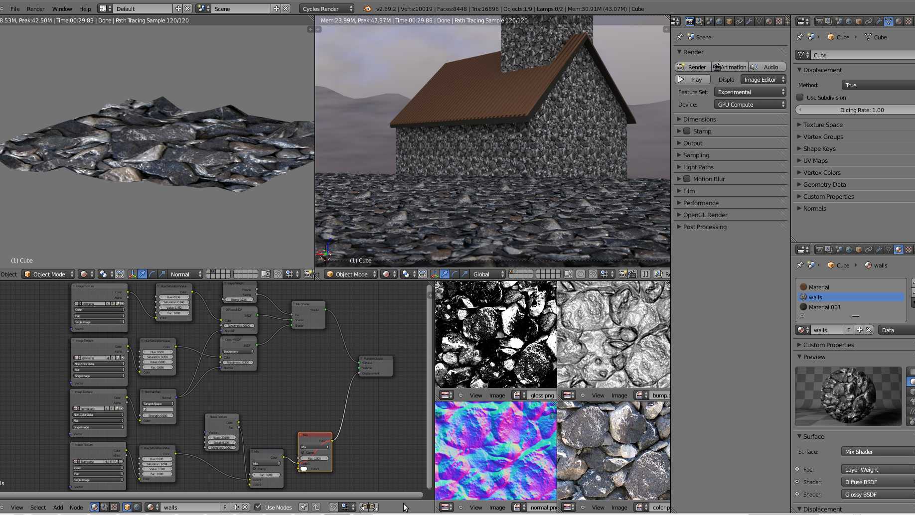
Create displacement using the shader
The shader displacement works a bit differently. Instead of using the modifier we use the displacement slot in the shader. However, this is limited to Cycles only for now.
The displacement socket in the material output node is configured to use bump mapping instead of displacement by default. We first need to change this.
Setup for shader displacement
In the properties panel, go to the shader tab and find the settings section. Here you will find a «surface» subsection with a dropdown setting called «displacement». Change this from «bump only» to «displacement only» or «displacement and bump» if you want to combine both effects.
Personally I always use «displacement only» and use the normal map for finer details.
If you can’t see these settings, make sure that you are in Cycles render engine in the render tab.
Once we changed this setting we can go to the shading workspace. Also make sure that you go to rendered preview mode in the top right corner of the 3D viewport so that we can see the effect the displacement has.
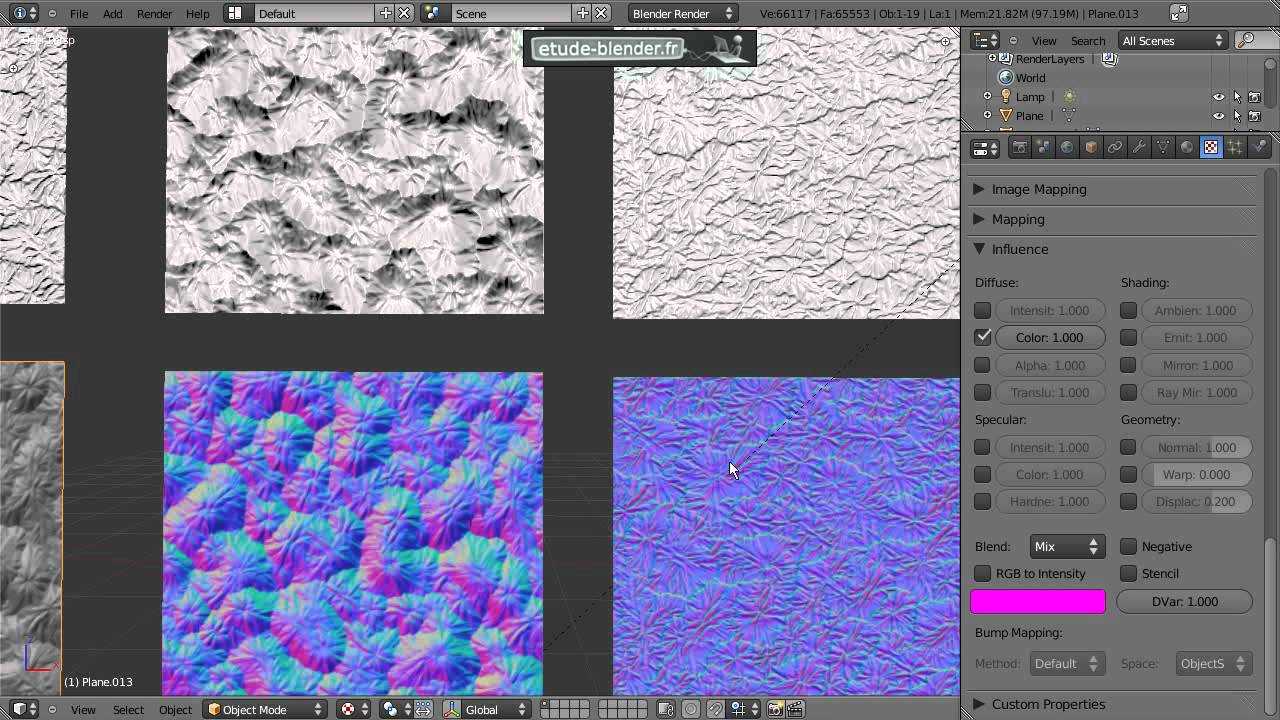
Node setup for displacement
In the node editor, we need a displacement node that we can find in the vector category in the add menu.
We also need either a displacement image texture or one of the procedural textures. Plug your texture into the height input of the displacement node and plug the displacement node to the material displacement output.
This is a minimal setup. But the good thing about the shader workflow is that we can combine multiple textures and if we need a manually painted mask we can use vertex paint to paint a back and white mask as opposed to a vertex group.
An easy way to control the strength and midlevel of a texture is to add two math nodes after the image texture. Set the first one to multiply and the second one to add.
Set the bottom value of the multiply node to 1 and the bottom value of the add node to 0 to nullify their effect then increase or decrease from there. The multiply node will be like a strength value or scale value while the add will act as an offset.
2D Mapping
These parameters are available only when 2D mapping (landscape) is selected as the Type.
Resolution – Explicitly sets the resolution of the displacement texture that V-Ray uses during the displacement process. If the texture map is a bitmap, it is best to match this resolution to the size of the bitmap. For procedural 2D maps, set the resolution according to the desired quality and detail in the displacement. Note that V-Ray also automatically generates a normals map based on the displacement map to compensate for details not captured by the actual displaced surface.
Tight bounds – When enabled, V-Ray computes more precise bounding volumes for the displaced triangles, leading to slightly better rendering times.
![]()
Изучаем основы
Displacement удобно применять там, где при моделировании вручную теряется много времени из-за сложной работы с сеткой. С помощью Displacement можно создавать сложные фактуры пола, элементы декора, а также модели экстерьера: траву, горный рельеф, протекторы шин.
![]()
В 3d max, при использовании визуализатора VRay, существует три способа работы с Displacement:
- применение карты Displace при создании текстуры объекта;
- наложение модификатора Displace на модель;
- или использование модификатора VRay DisplacementMod.
Все три способа действуют по одному принципу, но отличаются шириной функционала. Давайте поговорим о каждом отдельно.
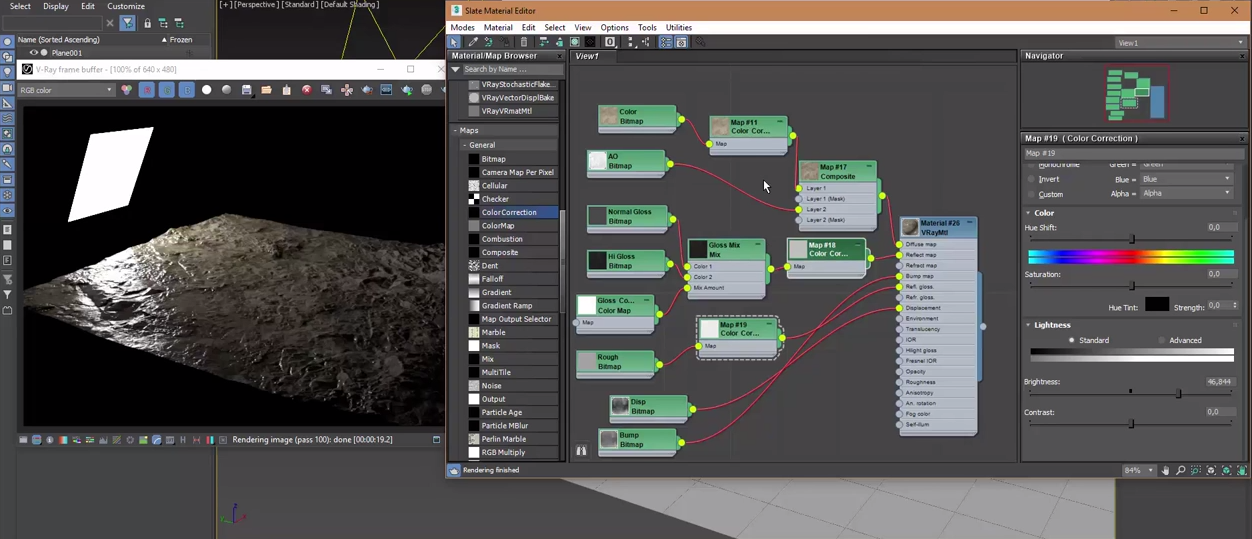
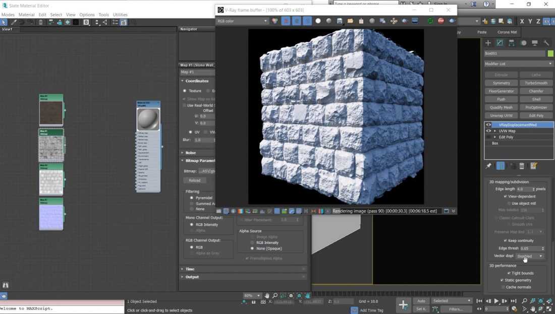
Логика создания карты трещины.
![]()
Вот такая сеть нод (дальше я будут карты (maps) называеть нодами, поскольку они соединяются в цепь нод) позволяет создать процедурную текстуру трещины в 3ds Max. Это я привёл скриншот из редактора материалов в режиме нод (Slate Material Editor). Если вы еще не перешли на нодовое отображение, то очень рекомендую. Это во много раз улучшает восприятие логики работы сложных материалов, а также убыстряется процесс работы с материалом.
Чтобы переключится в этот режим вам нужно -> открыть редактор материалов (клавиша M) -> в верхнем меню выбрать пункт Modes (режимы) -> переключиться с Compact Material Editor на Slate.
Теперь собственно объясняю логику. Читаем сеть нод слева направо.
За основу я взял карту BerconNoise (обозвал её JustNoise). Потом эту карту смешал саму с собой с помощью ноды Composite (обозвал её Difference, поскольку режим смешивания нужен Difference). Только на один вход ноды Composite я подал оригинал, а в другой слот — инвертированную версию (инвертировал с помощью стандартной ноды Color Correction, которую назвал Invert). И в конце, с помощью ноды ColorCorrect (это отдельный бесплатный плагин, который можно ) я обрезал величины цвета так, чтобы только трещина осталась чёрной, а всё вокруг неё стало белым.
Common Params
These parameters are common to all types of displacement.
Texmap – The displacement map. This can be any texture map such as a bitmap, procedural map, 2D or 3D map, etc. This option is ignored if Use object mtl is enabled.
Texture chan – The UVW channel that is used for displacement mapping. This must match the texture channel specified in the texture map itself, if it uses explicit UVW mapping. This is ignored if the Use object mtl option is enabled.
Filter texmap – When enabled, the texture map is filtered. This option is ignored if the Use object mtl option is enabled.
Filter Blur – The strength of the filter applied to the map.
Amount – The amount of displacement. A value of 0.0 means the object appears unchanged (or simply smoothed, if the Subdivision method is selected). Higher values produce a greater displacement effect. This value can also be negative, in which case the displacement pushes geometry inside the object.
Shift – Specifies a constant which is added to the displacement map values, effectively shifting the displaced surface up and down along the normals. This value can be either positive or negative. For more information, see the below.
Water level – This value clips the surface geometry in places where the displacement map value is below the specified threshold. For more information, see the below.
Relative to bbox – When this option is enabled, the displacement height is based on the bounding box of the objects, the way 3ds Max performs displacement by default. When this option is disabled, displacement height is expressed in generic world units where white areas in the displacement map correspond to a displacement of 1 generic unit.
Texmap min/max – These two options specify custom boundaries for the displaced geometry. By default, they are limited to values between 0 and 1. For more information, see the below.
![]()
Example: Shift
Note that the Shift parameter is an absolute value in world units. If you change the Amount, you will probably need to adjust the Shift too.
![]()
Shift = -10.0
![]()
Shift = -5.0
![]()
Shift = 0.0
![]()
Shift = 5.0
![]()
Shift = 10.0
-10.0
10.0
Example: Clip Mapping
The Water level parameter is absolute in world units. For this example, Amount is set to 5.0 and Shift is set to 0.0. Note that when Water level reaches Amount + Shift, all geometry is clipped.
![]() Water level = 0.0 (no clipping)
Water level = 0.0 (no clipping)
![]() Water level = 1.25
Water level = 1.25
![]() Water level = 2.5
Water level = 2.5
![]() Water level = 3.75
Water level = 3.75
![]()
Water level = 5.0 (all geometry is clipped)
0.0
5.0
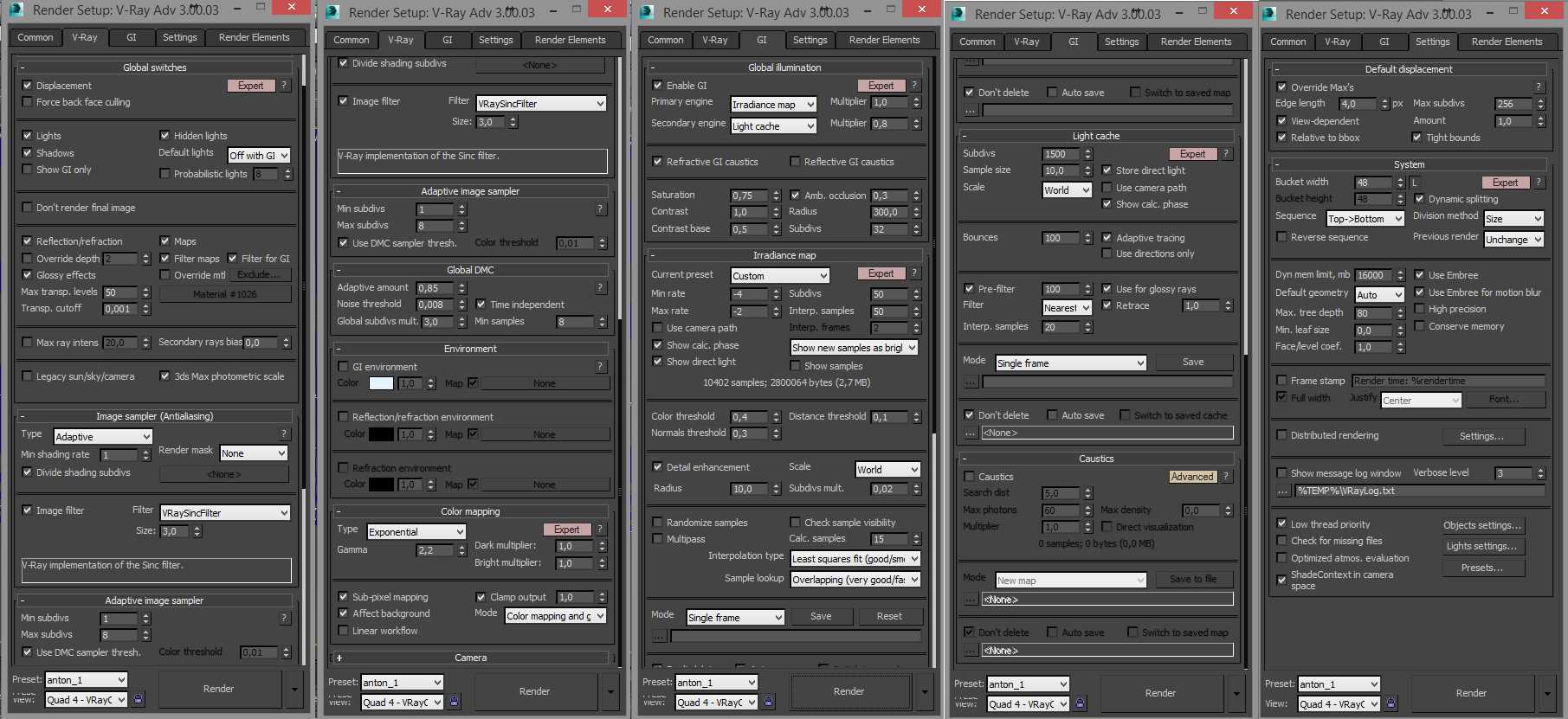
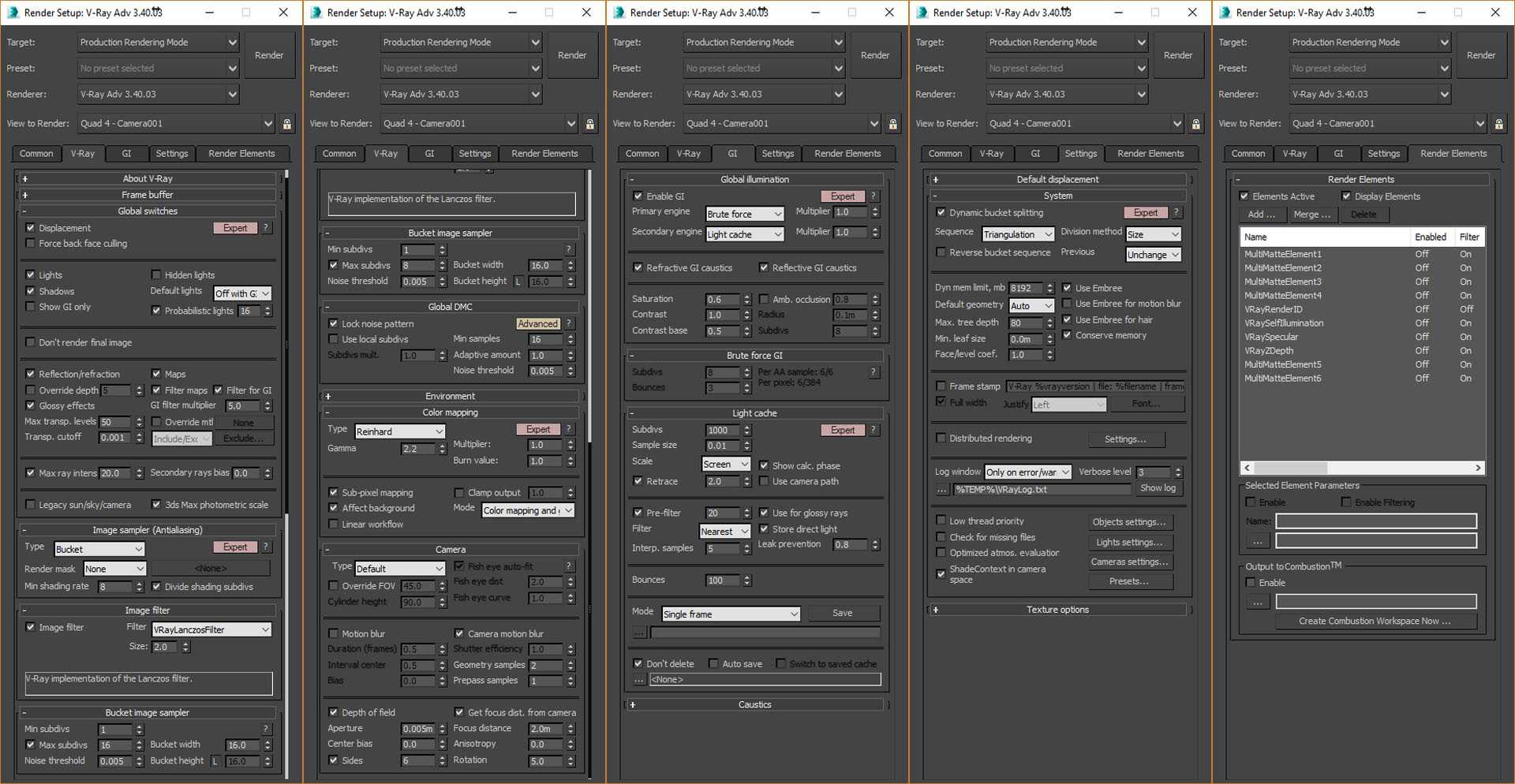
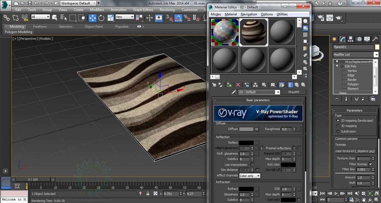
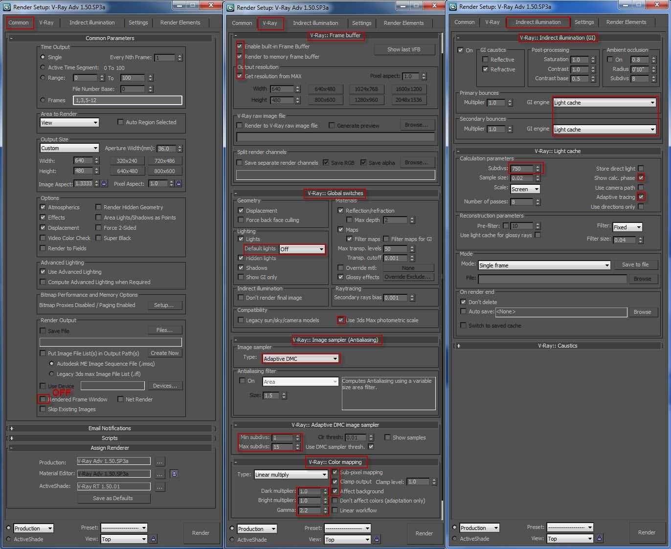
Where to set up Displacement in 3ds Max and V-Ray
There are two methods of setting up displacement in 3ds Max and V-Ray.
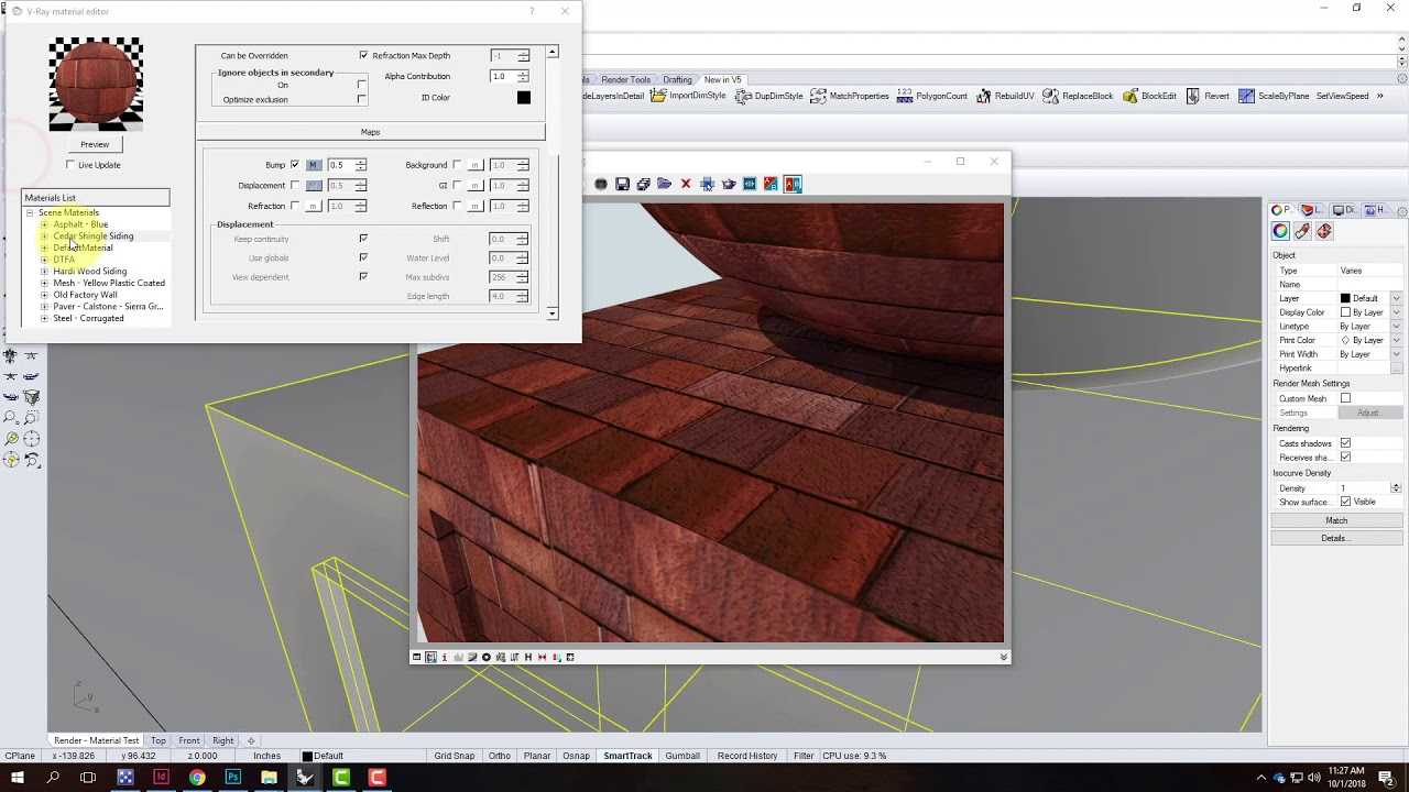
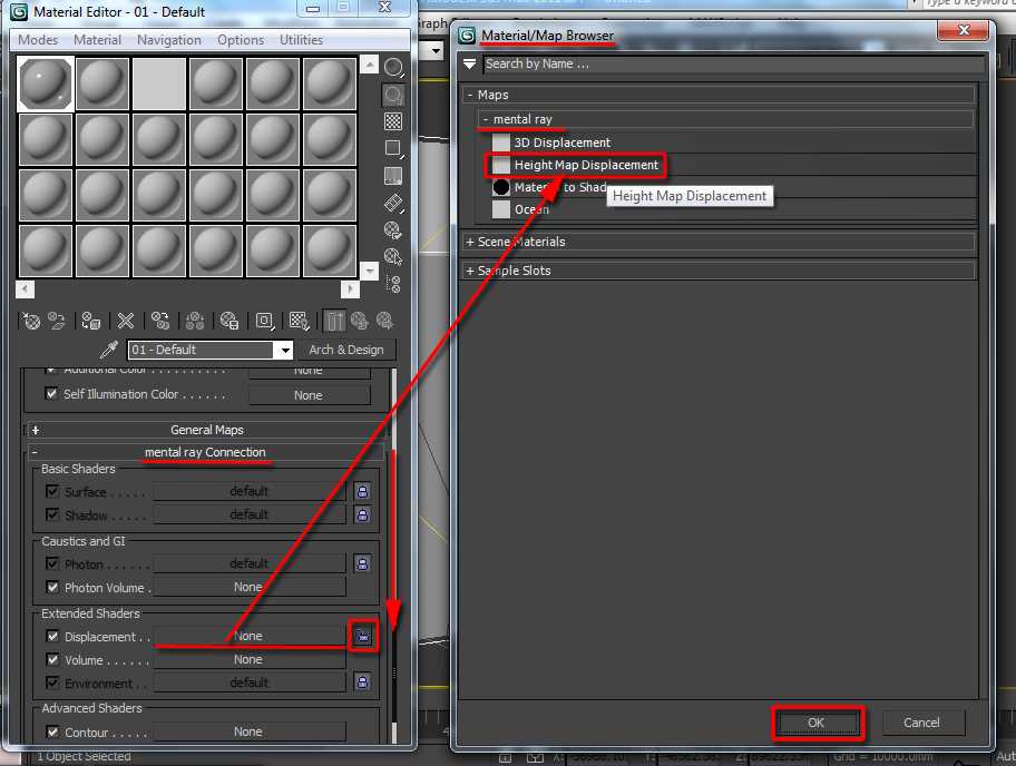
The first is to set it in Render Setup (V-Ray) -> Settings -> Default displacement in conjunction with Material Editor -> Maps -> Displace
![]()
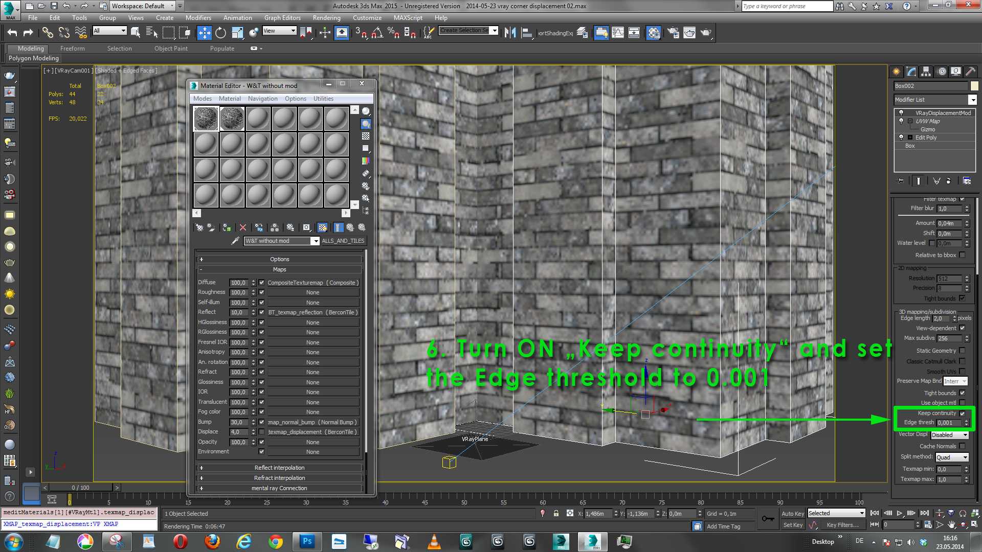
The second way is adding the VrayDisplacementMod modifier and linking a map from Material Editor to the “Texmap” slot (as Instance)
![]()
Using the VRayDisplacementMod modifier provides more flexibility in setting up displacement features and managing resources necessary for rendering.
Displacement features settings – These influence render times and RAM used by the scene. They need to be set to specific values to get the exact look of the displaced model you want. Therefore, these values should not be compromised for the sake of optimization. Please turn to the other settings listed below instead.
Quality settings – These set the displacement’s level of detail, number of subdivisions, and mesh density. They are decisive in the number of resources your scene needs for rendering, and we will optimize them in the next chapters of the guide.
Performance and other settings – These are special settings that affect rendering performance; they can be used in rare scenarios for debugging displacement-related issues, like artifacts or unusually high resources usage. We will talk about them at the end of the guide.
According to the V-ray manual, there are three types of mapping in VRayDisplacement Mod:
- 3D mapping – A general method that takes the original surface geometry and subdivides its triangles into smaller sub triangles which are then displaced.
- 2D mapping – Bases the displacement on a texture map that is known in advance. The displaced surface is rendered as a warped height-field based on that texture map. The actual raytracing of the displaced surface is done in texture space, and the result is mapped back into 3D space.
- Subdivision – Similar to the 3D mapping method, with the difference that it applies a subdivision scheme to edges (similar to a MeshSmooth modifier). We will skip that method in this guide.
We will use VrayDisplacementMod modifier setup for tests because it has all the options which displacement from render settings provide and more, and it allows you to set displacement options separately for each model in a scene.
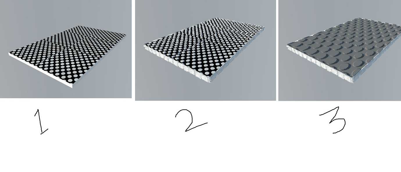
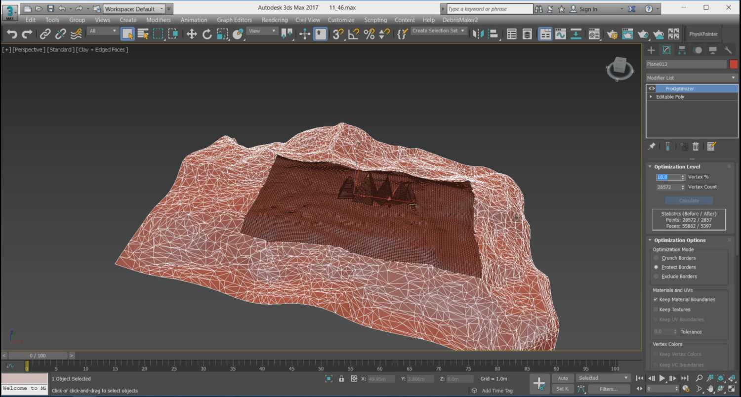
We will use various variants of the scene below for tests.
![]()
The test scene contains three boxes with VRayDisplacementMod added. GI is set to Brute Force + Light Cache
Tests setup:
Hardware: Intel V2 processor, 2.80 GHz, 128 GB RAMSoftware: 3dsMax 2017 + V-ray 4.10.02GI was set to Light Cache + Brute Force, default settingsAll other settings were left as default.
Credits
This guide has been created by Michał Moś and edited with the help of the team at GarageFarm.NET. We derived most of the knowledge used in this guide from an extensive experience running a render farm for almost a decade as well as from the Autodesk Knowledge Network and Chaos Group V-ray documentation. Textures used in the tests are from https://www.textures.com/ and https://3dbee.it/.
![]()
Michał Moś ( aka ‘Andrew’ ) is part of GarageFarm.NET team specializing in 3d rendering topics from animation and troubleshooting to technical writing. He has worked for numerous design and architectural companies as a CG artist, designer, and instructor. Weapon of choice – 3ds Max, C4D, V-Ray and Octane. He loves drawing, creative writing, and tabletop RPGs.
https://michalmos.carbonmade.comhttps://blog.garagefarm.net/
FLOATING-POINT VS INTEGER
Процедура, описанная ниже, предполагает создание 32-битных карт displacement, однако также можно использовать и 16-битную карту displacement типа floating-point, что позволит получить практически идентичный результат.
Убедитесь, что вы сохраняете карту displacement в 16-битном формате типа floating-point, а не в 16-битном формате типа integer. Чтобы формат integer сработал корректно, придется немало поплясать с бубном. И все потому что этот формат не поддерживает данные с отрицательными значениями, с которыми легко работают карты displacement. Если вы уже задумались, как получить ту или иную карту, просто следуйте инструкции, описанной ниже, чтобы создать 32-битную карту displacement.
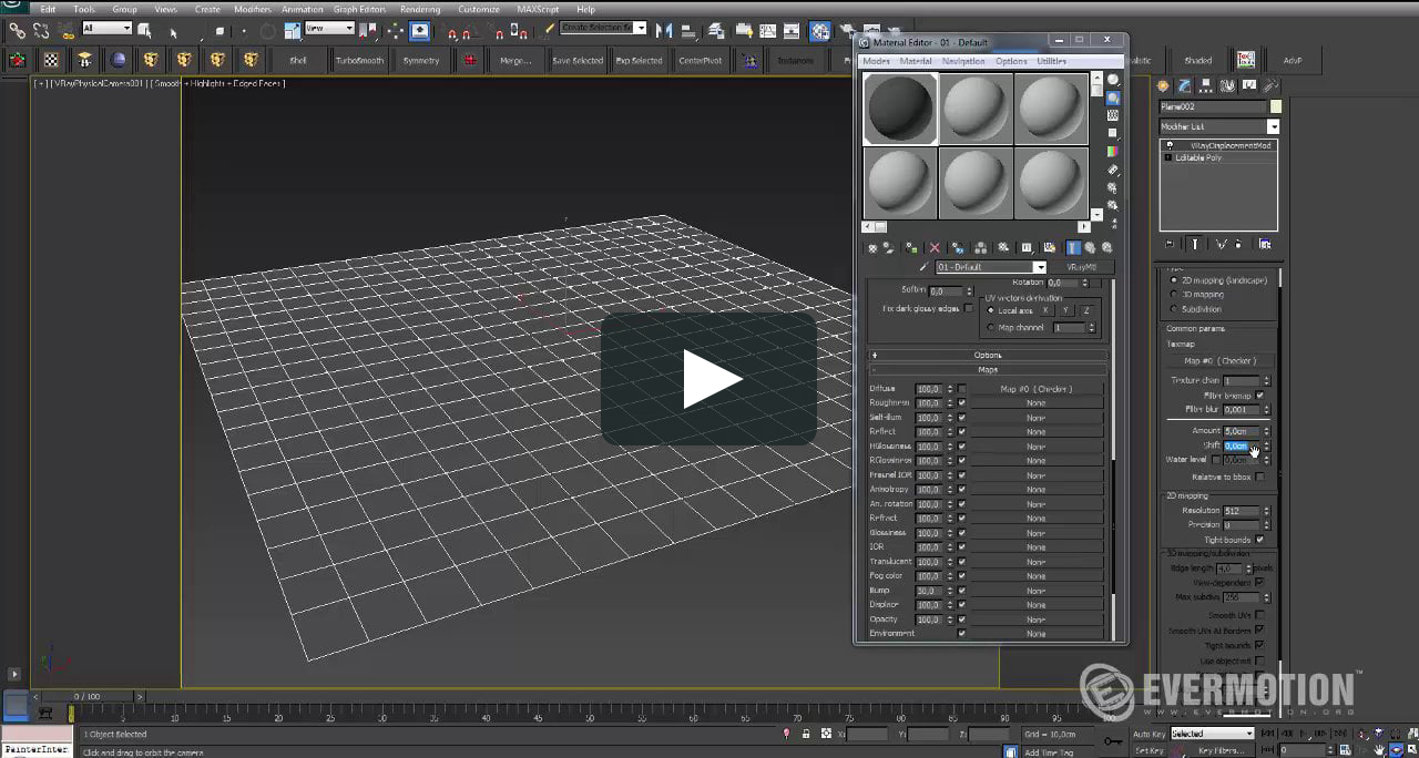
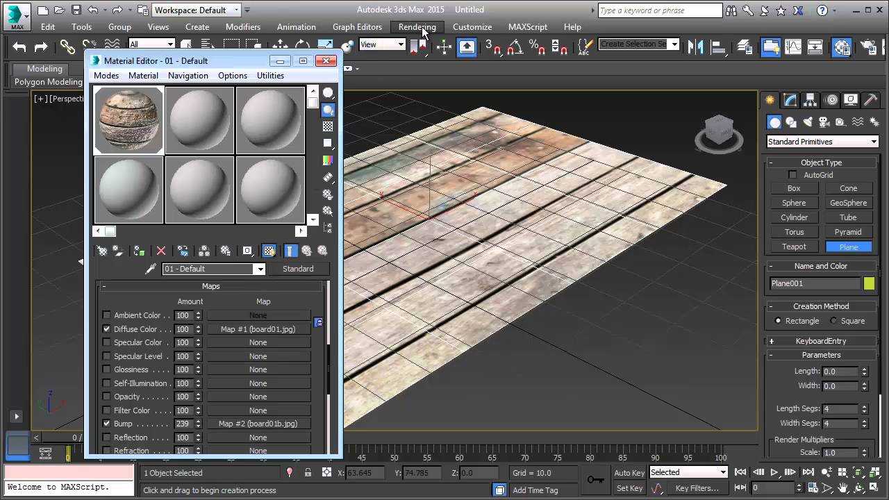
Создание рельефа
Прежде всего необходимо создать высокополигональный объект. Чем больше будет полигонов, тем выше окажется качество проекции рисунка. Затем нужно перейти в Modify – Modifier List – Displace.
![]()
В разделе Image задается текстура, по которой создастся рельеф. Нажав кнопку None в подразделе Map, можно будет выбрать любую стандартную карту 3ds Max. В подразделе Bitmap устанавливается любое стороннее изображение. Кнопками Remove Map/Bitmap назначенные карты удаляются.
Как только изображение будет назначено, нужно изменить значение Strength. Этот параметр влияет как на силу выдавливания, так и на направление.
Luminance Center изменяет смещение геометрии. По умолчанию полигоны объекта либо смещаются (в светлых областях рисунка), либо остаются на месте (в темных областях). Параметр Center позволяет управлять, какой цвет и с какой силой будет сдвигать полигоны.
Blur размывает границы между светлыми и темными областями рисунка. Чем сильнее Blur, тем более сглажены края. Слишком большие значения этого параметра размывают весь рисунок.
![]()
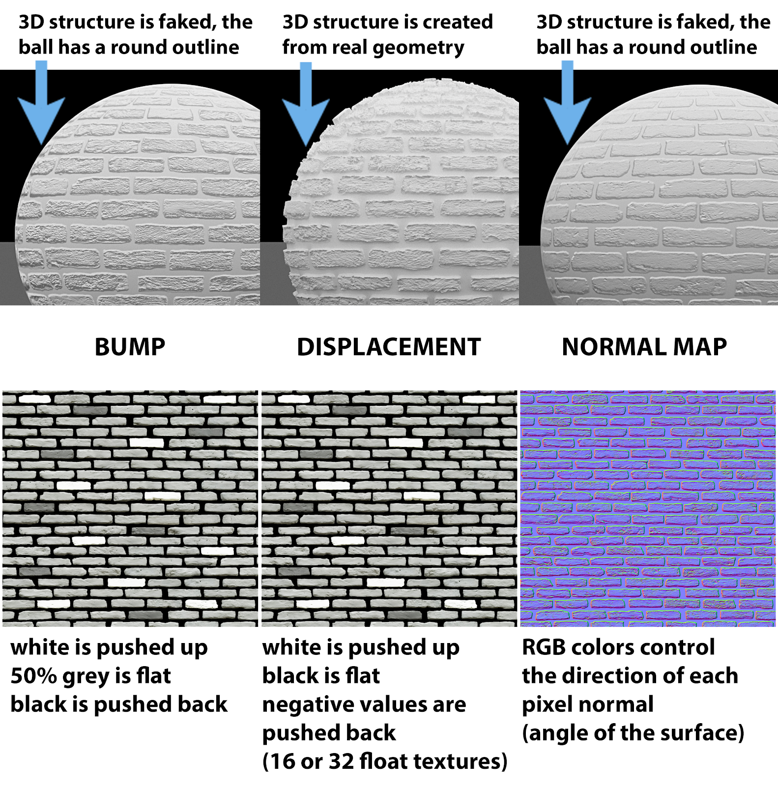
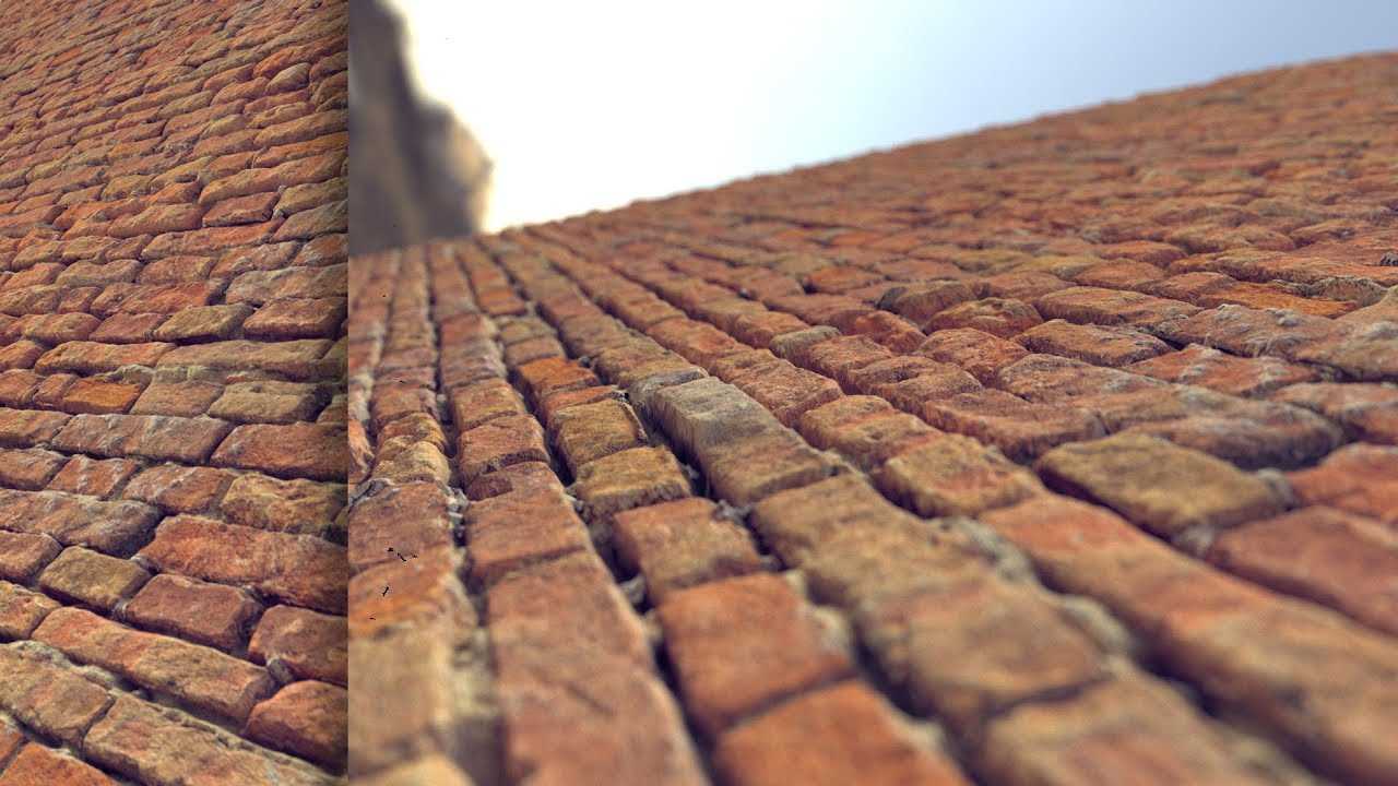
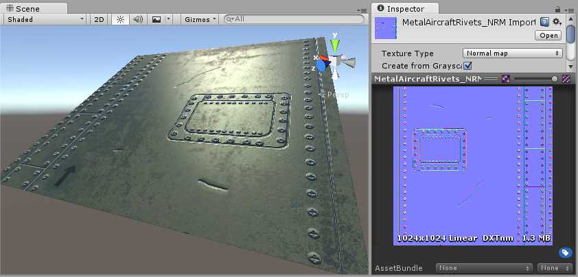
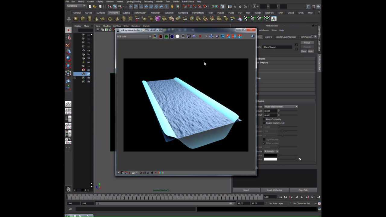
When do we use displacement?
The most common scenario where we use displacement is to give a surface a kind of mid level detail that would be too time-consuming to sculpt or model.
But displacement also requires a lot of geometry to be able to displace enough to create the detail. Therefore, if the detail we want to create is too small we may be better of using a normal map instead.
Displacement can also change the silhouette of an object and if that is our objective a normal map is not enough.
So you can see that a displacement texture lives somewhere in the mid level detail area and can be a good option if we want detail in the silhouette.
Since displacement needs a lot of geometry it is also heavy on performance. Therefore, you don’t see displacement maps used as often for real-time applications or games.
Subdividing displacements
The Subdivide button on the Displacement tab can be used to smooth two or more selected displacement surfaces in relation to their position. To subdivide two or more displacements, select the displacement faces that should be subdivided and press the Subdivide button. If the subdivision is not successful, you’ll see areas where displacement faces appear buggy and out of place.
Tip: The higher the Power attribute is, the smoother the displacements will be. However higher Power is heavier for game engine and therefore using high Power for small displacements is not recommended.
![]()
A series of interconnected brushes ready to be created into displacements.
![]()
The tunnel after displacements are created.
![]()
What occurs when subdivision occurs among the selected displacements.
![]()
A finished product with some touch-ups using the Paint Alpha tool


